
Time for some proto test results!
Proto 1 propeller
Not much to say about this one. We did a initial test run with this propeller, and found out that our very first boat drag guess was off by a lot. The acceleration was slower than the "quality aftermarket" stainless propeller we were comparing to, and we only got about a 0-1km/h top speed improvement.
We were quite surprised with the top speed increase, even though our design values where off by quite a lot. This raised hopes that our design had some serious potential, with quite a different design philosophy compared to propellers on the market now.
But we did get valuable test data, as well as realizing we would need more accurate GPS data to evaluate the results better.
Proto 2 propeller
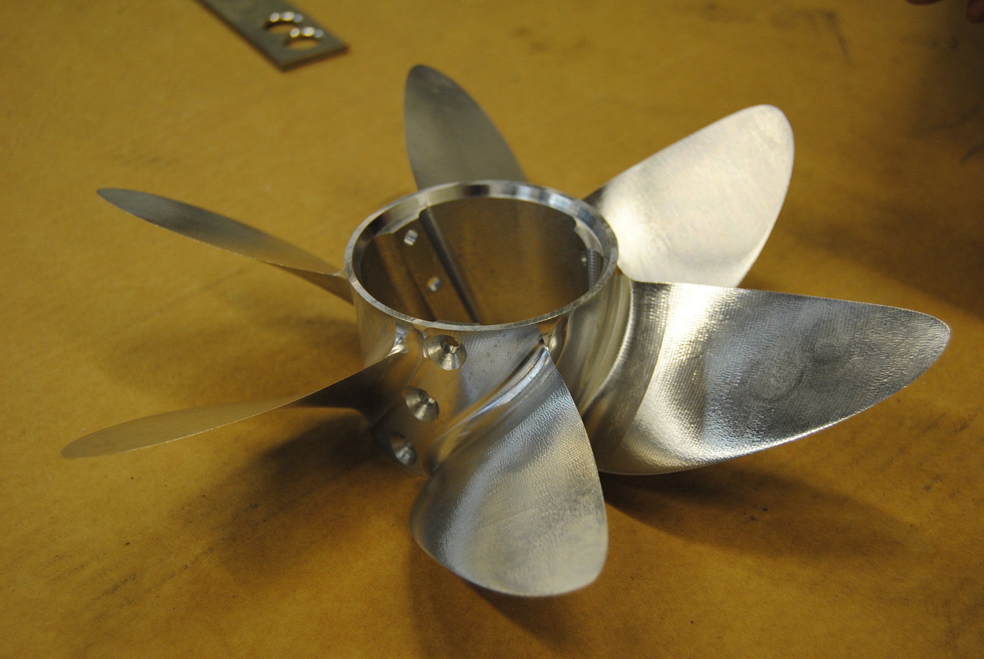
Now we had a serious propeller, with a design based on actual speed and slip values from the boat we were testing on. Our confidence level was much higher than with the proto 1 propeller. The manufacturing process we use, allowing for super-thin blades, really changes the way you can look at the design process.
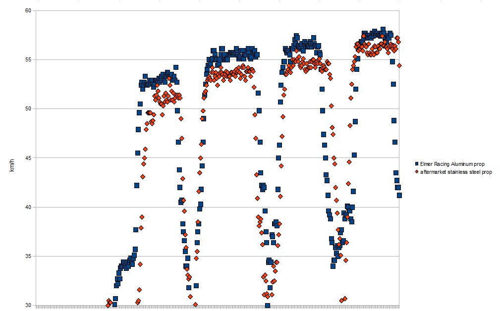
And the awesome test results. They are not fully valid though, since the engine was pulling much more rpm with our proto 2 propeller than with the benchmark. And we had no idea of what the powerband on our 45hp 4-stroke Honda engine looked like. But anyway, a serious speed increase:
Proto 3 propeller
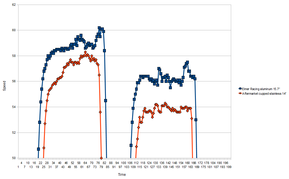
With this propeller we wanted to get the engine running at the same rpm as the reference prop. 15.7" of pitch was just right! 6000rpm with a tailwind, and about 5800rpm in a headwind, with both our proto 3, and the reference prop.
That means this is a genuine, fully comparable result. Our proto3, 6-blade billet CNC aluminum propeller accelerates faster, and gives a average of 2km/h top speed increase over a high quality cupped stainless steel propeller. Huge!
- Details
We're not really sure where the initial idea came from. But we noticed that even typical "performance" boat propellers didn't seem to be that well designed. The design process used by the leading manufacturers seemed to be mostly trial-and-error, as well as a traditional "black-art" type design.
We started wondering how much of a performance increase there would be to have, by moving away from the experience / "black-art" based design process, to a more scientific method. Surely there must be many % of improvement available?
We decided to find out!

Having some knowledge of hydrofoil operation from our X-1 ground effect vehicle testing and rotational profile physics from doing some Sikorsky Challenge calculations, we had a good starting point to do some initial physics guesses. The biggest unknown was how much drag our test boat had, and hence how much reaction force would need to be produced by the propeller. The higher the reaction force for the blade area, the higher the slip. Slip means efficiency losses.
On the other side of the optimization curve we have blade drag. Larger then optimum blades produce more drag losses than what they reduce slip by.
So we needed to get values for the slip amount we where going to be running with our test boat flat out. We had no way of getting these values, so we where simply going to have to measure it, by testing different propellers.
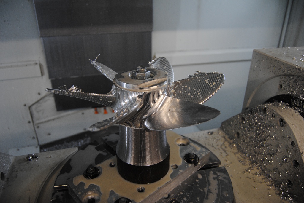
We started designing our propeller dimensioning tool (basically just a fancy calc sheet), and from that designed the actual model with our SolidWorks CAD software. Once we had the model dimensions done we ordered in some billet aluminum raw material. While waiting for the raw material, we imported the CAD model into our PowerMILL CAM program to design the milling process, to actually manufacture the propeller.
Test results in future articles!
- Details